Daytona USA 2 PCB on the way

Discuss Supermodel and your favorite Model 3 games. Show off your latest threads, this is the place to see and be seen.
Forum rules
Keep it classy!

  • No ROM requests or links.
  • Do not ask to be a play tester.
  • Do not ask about release dates.
  • No drama!

Re: Daytona USA 2 PCB on the way

Postby Ian » Tue Aug 18, 2020 1:09 pm

cheap pci-e network card? :)

My current thoughts are ..
Could either have a toslink splitter, then wire up something like a toslink receiver part, think they are a few quid or something. Then would need some sort of USB based data acquisition card. Something to just read the voltage on the output pin of the receiver. Either that or probe the pin on the board directly.

Not sure what could be used for data acquisition. I think we need to sample at a pretty high frequency.
Ian
 
Posts: 2044
Joined: Tue Feb 23, 2016 9:23 am

Re: Daytona USA 2 PCB on the way

Postby model3man » Wed Aug 19, 2020 12:25 am

I haev a couple daytona2 bote boards. Once I make a second power harness I can run both at the same time. I have 1 toslink cable, but I think you need 2 as toslink is unidirectional.
I believe the units are wired in a token ring arrangement.

I have a saleae logic pro I can use to sample both unit's TX line at 500msps. Just gotta get everything set up.
You can then develop a custom analyzer DLL for the pc software to decode the protocol as you figure it out. (I can make logs then upload them)
model3man
 
Posts: 24
Joined: Mon Jul 13, 2020 4:15 am

Re: Daytona USA 2 PCB on the way

Postby Ian » Wed Aug 19, 2020 4:59 am

I have a saleae logic pro I can use to sample both unit's TX line at 500msps. Just gotta get everything set up.


That's a very nice bit of kit .. expensive too. I think that should definitely be able to do the job.
Ian
 
Posts: 2044
Joined: Tue Feb 23, 2016 9:23 am

Re: Daytona USA 2 PCB on the way

Postby Bart » Fri Aug 21, 2020 5:54 pm

Daytona 2 arrived the other day. I haven't unpacked it yet. I hope to fire it up tomorrow or Sunday using my existing power harness. I assume that the filter board is identical to Step 1.0 but I'll try to find a pinout and compare just to be extra sure.
User avatar
Bart
Site Admin
 
Posts: 3086
Joined: Thu Sep 01, 2011 2:13 pm
Location: Reno, Nevada

Re: Daytona USA 2 PCB on the way

Postby Bart » Sat Aug 22, 2020 10:12 pm

JST connectors arrived from Japan. Thanks for those part numbers, model3man! :) I'll see if I can scrounge up some wire around here to connect my Sega 6-button pad decoder to my VF3 board tomorrow. Haven't handled a crimping tool in years now!
User avatar
Bart
Site Admin
 
Posts: 3086
Joined: Thu Sep 01, 2011 2:13 pm
Location: Reno, Nevada

Re: Daytona USA 2 PCB on the way

Postby Conversus W. Vans » Wed Apr 21, 2021 5:56 pm

Sorry for the bump but I got a Model 3 Step 2 PCB from Yaton in China that had the Harley-Davidson ROMs. My original goal/plan was to wire up a simple racing wheel that uses 5k pots so I can play Model 3 drivers, but then my friend decided to strip a Harley cab he got from a warehouse, and sold me the entire control panel with the original wooden box, which I later got strapped to a plant dolly with plumbing brackets. When my first board arrived, I'd later found out through a couple fellows that my filter board was incompatible, given it was a conversion from another game -- Virtua Striker 2. Its filter board did not have a 10-pin 5v output connector populated, which I believe is required for inputs and potentiometers on all the platform's racing games. Replaced it with a Daytona 2 one, and viola -- controls work awesomely!

I had actually purchased two full board stacks of that game, and they BOTH had issues coming from the CPU board -- one without sound, and the other WITH sound but steering was completely erratic when turning left; it made the game almost completely unplayable for me! After applying some hot air across certain ICs on both boards, that "fixed" the problem but a day or two later, both my CPU boards had wet the bed with the same issues I had prior, and from what Ken himself told me, hot air destroys Sega surface mount chips. One of the CPU boards actually got corroded so I ended up throwing it in the garbage, and the other I've saved to clean excess solder from the attempts I did to get sound back. Since I am not risking frying my game, I ended up buying a fresh "tested" CPU board altogether.

On the Daytona 2 spectrum, I'm really after a ROM kit, or board + security chip for either Battle on the Edge or Power Edition, to use my Dreamcast Race Controller with. Several of them are floating around the Internet at various prices. I'd have to sacrifice manual transmission since that game uses a stick, and I probably won't be tracking down the DSB2 sound board until after I get everything running. Because it has no pedals, I hear it's a very easy wheel to use for Model 3 and JVS-based Sega h/w. In case I get tired of LA Riders it'd be nice to mix things up with a li'l DUSA2 since it's my 2nd fav Model 3 game of all time. Fingers crossed on the CPU board replacement, as maintaining these boards has been a challenge for me.
"We're cowboys on the freeway." - Masanori Takeuchi, 1997
User avatar
Conversus W. Vans
 
Posts: 277
Joined: Sun Apr 27, 2014 3:27 pm
Location: Grubnatraps, South Carolina

Re: Daytona USA 2 PCB on the way

Postby sonic32 » Thu May 06, 2021 3:37 am

THANK YOU, I've already found the answer, so I deleted the post. ;)
User avatar
sonic32
 
Posts: 169
Joined: Tue Dec 20, 2011 11:43 am
Location: Slovakia

Re: Daytona USA 2 PCB on the way

Postby Conversus W. Vans » Tue Jun 01, 2021 5:42 pm

A little update. I was able to make me a little Model 3 racing wheel using a hacked Dreamcast HKT-7400. It works well with the platform's drivers but you're pretty much stuck using auto transmission on most games, and this wheel has no pedals. But it's a great and easy wheel to mod for game collectors who want to play Model 3 stuff.

To use this wheel you open it up with the 4 bottom screws, then as long as you twist the red and black wires (respectively from the 3-pin/steering and 9-pin connector) for 5v, and both your grounds from steering and 9-pin, you should be able to wire up the pots and buttons going directly to the Model 3 filter board.

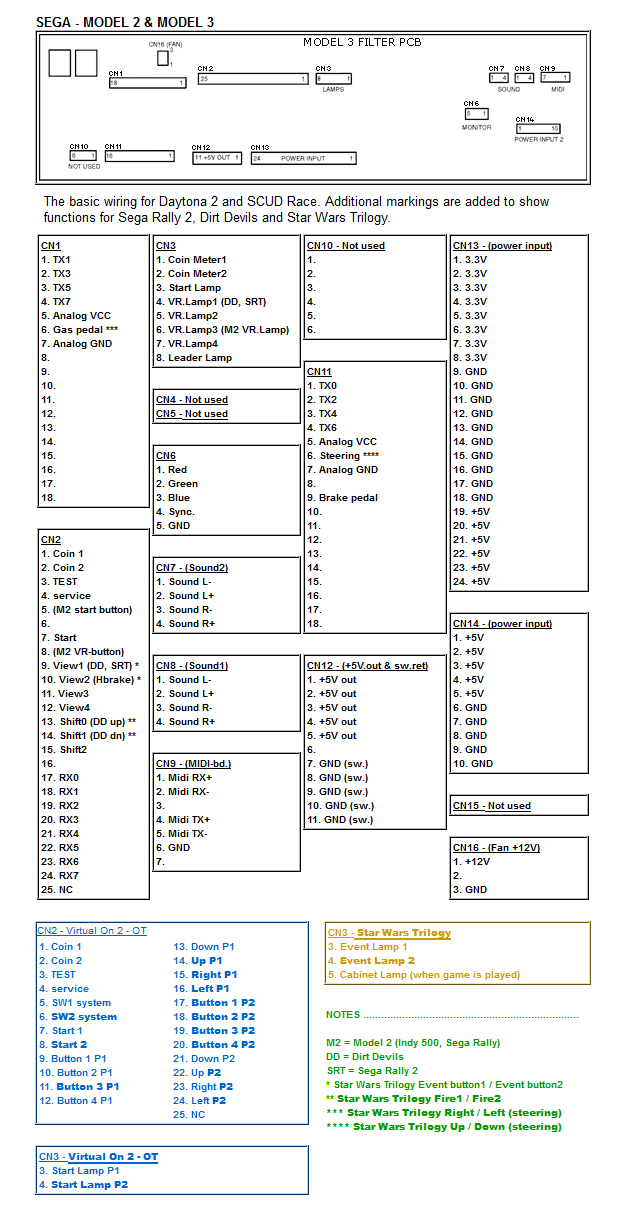
The two 5v wires need to be tied and connected to both the 5v signals on CN1 and CN11 of the Model 3's filterboard (pins 5 of both connectors). You need to do the exact same for the ground (pins 7 of the connectors). So far I've only tried it with Harley, which for that game you'll need to tie the rear & front brakes together or else one of the brakes goes full on when the other is depressed.
After tying these connections, buttons and analog inputs should connect straight-through. I'd recommend tracking a wiring harness from a Daytona 2 or ScudRace cabinet as it will likely have the amount of connectors and wires you need to wire up your controls. I use a set of crimp connectors, solder seal connectors, and 22-24 awg wire for this. Wire strippers that support as small as 28 awg (the size of wires the DC Racing Wheel uses), a standard crimper, and heat gun are recommended too.

I've got a Daytona 2 ROM board & security chip as well, but as I'm waiting on a replacement CPU Board, I cannot play that right now.

You'll need to be careful when doing this mod as I've had the wires come off the lugs of the steering potentiometer, and I can honestly tell you soldering it back on there can be a pain since if it's not soldered on there well enough, your steering will likely be janky unless you insulate it well.

And just a safety reminder: NEVER EVER(!!!) solder wires when your game is powered on by the way. Total shock hazard.

Here's a little wiring diagram I found for most Model 3 games. I forget who made this but it was on Arcade Otaku:
Image
"We're cowboys on the freeway." - Masanori Takeuchi, 1997
User avatar
Conversus W. Vans
 
Posts: 277
Joined: Sun Apr 27, 2014 3:27 pm
Location: Grubnatraps, South Carolina

Previous

Return to The Catwalk

Who is online

Users browsing this forum: No registered users and 1 guest