I've been tinkering around with Supermodel and studying the disassembly of games to try and understand how JTAG is supposed to work on Model 3, and I think I've finally got at least a rough idea.
Right now Supermodel is emulating just one JTAG device with crazy long instruction and data registers; 46 bits and 197 bits respectively. But the real Model 3 video board consists of many JTAG-compatible devices daisy-chained to one another; namely, the individual ASICs (Mercury, Venus, Earth, etc.). By running the video RAM tests and seeing what popped up in the JTAG instruction register, I was able to ascertain that each ASIC has a 5-bit instruction register. For example, the combined IR code 0x3e8fffffffff translates to binary as 11111 01000 11111 11111 1111 11111 11111 111111111111 - sending 11111 (the BYPASS instruction) to each of the ASICs except for Mercury, which receives 01000 (not sure what this does just yet). In fact, the combined IR code 0x06318fc63fff translates to binary as 00011 00011 00011 00011 1111 00011 00011 111111111111 - sending 00011 (which must be the optional IDCODE instruction) to all of the ASICs.
But then we're left with sixteen bits unaccounted for: four between Earth and Mars, and twelve at the end. These are always set to 1 except when running a boundary scan. Well, I was able to find this document on the Mitsubishi 3D-RAM and it turns out the 3D-RAM units are also JTAG-compatible; mystery solved! Indeed, the combined IR to start a boundary scan is 0xa2205021444, or 00101 00010 00100 00001 0100 00001 00001 0100 0100 0100 - sending 0100 to each of the 3D-RAM units, which is the SAMPLE/PRELOAD instruction.
So the proper way to emulate JTAG on the Model 3 would be create an array of 10 JTAG device objects, with the TDO of each one feeding into the TDI of the next:
Jupiter -> Mercury -> Venus -> Earth -> 3D-RAM -> Mars -> Mars -> 3D-RAM -> 3D-RAM -> 3D-RAM
If we wanted to emulate the Step 2.x video board, we add more objects to the chain for a total of 17:
Jupiter -> Mercury -> Venus -> Earth -> 3D-RAM -> Mars -> Mars -> 3D-RAM -> 3D-RAM -> 3D-RAM -> Earth -> 3D-RAM -> Mars -> Mars -> 3D-RAM -> 3D-RAM -> 3D-RAM
I've started work on implementing such a system but I probably won't have that much time to work on it until the weekend.
P.S. Sega Rally 2 and Star Wars Trilogy Arcade fail to boot because they attempt to write data to a specific ASIC via JTAG and then read it back to make sure it worked. Because the games never receive back the value they just wrote, they just end up spinning in a loop forever, hence the need for patches to get the games to boot. If we emulate the proper JTAG daisy-chain system, it should be pretty easy to get both games working with no patches at all.
How to implement JTAG properly
Forum rules
Keep it classy!
Keep it classy!
- No ROM requests or links.
- Do not ask to be a play tester.
- Do not ask about release dates.
- No drama!
12 posts
• Page 1 of 2 • 1, 2
How to implement JTAG properly
![]() by gm_matthew » Thu Feb 03, 2022 9:00 am
by gm_matthew » Thu Feb 03, 2022 9:00 am
- gm_matthew
- Posts: 224
- Joined: Fri Oct 07, 2011 7:29 am
- Location: Bristol, UK
Re: How to implement JTAG properly
![]() by Bart » Thu Feb 03, 2022 1:25 pm
by Bart » Thu Feb 03, 2022 1:25 pm
This is fantastic! I was always puzzled by the length of the instruction and data registers but I never dug too deeply into the JTAG protocol besides the basic state machine. Did you disassemble and study some of the games' actual JTAG code?
Being able to understand what each specific ASIC is getting will help us understand what that command should do. For example, we believe there is a way to configure shading (we have one such command emulated) and this should really help there. I have a feeling that some tile gen config registers might only be exposed through JTAG, too.
Since the structure of Supermodel doesn't correspond 1:1 to ASICs, it probably makes sense to have a single generic JTAG class and instantiate multiple objects connected to each other explicitly. Commands can be handled by registering callbacks from the appropriate parts of the emulator. For example, Real3D.cpp, which I think currently has a hook for the shading setting.
-

Bart - Site Admin
- Posts: 3086
- Joined: Thu Sep 01, 2011 2:13 pm
- Location: Reno, Nevada
Re: How to implement JTAG properly
![]() by Ian » Thu Feb 03, 2022 2:03 pm
by Ian » Thu Feb 03, 2022 2:03 pm
Great work Matthew 
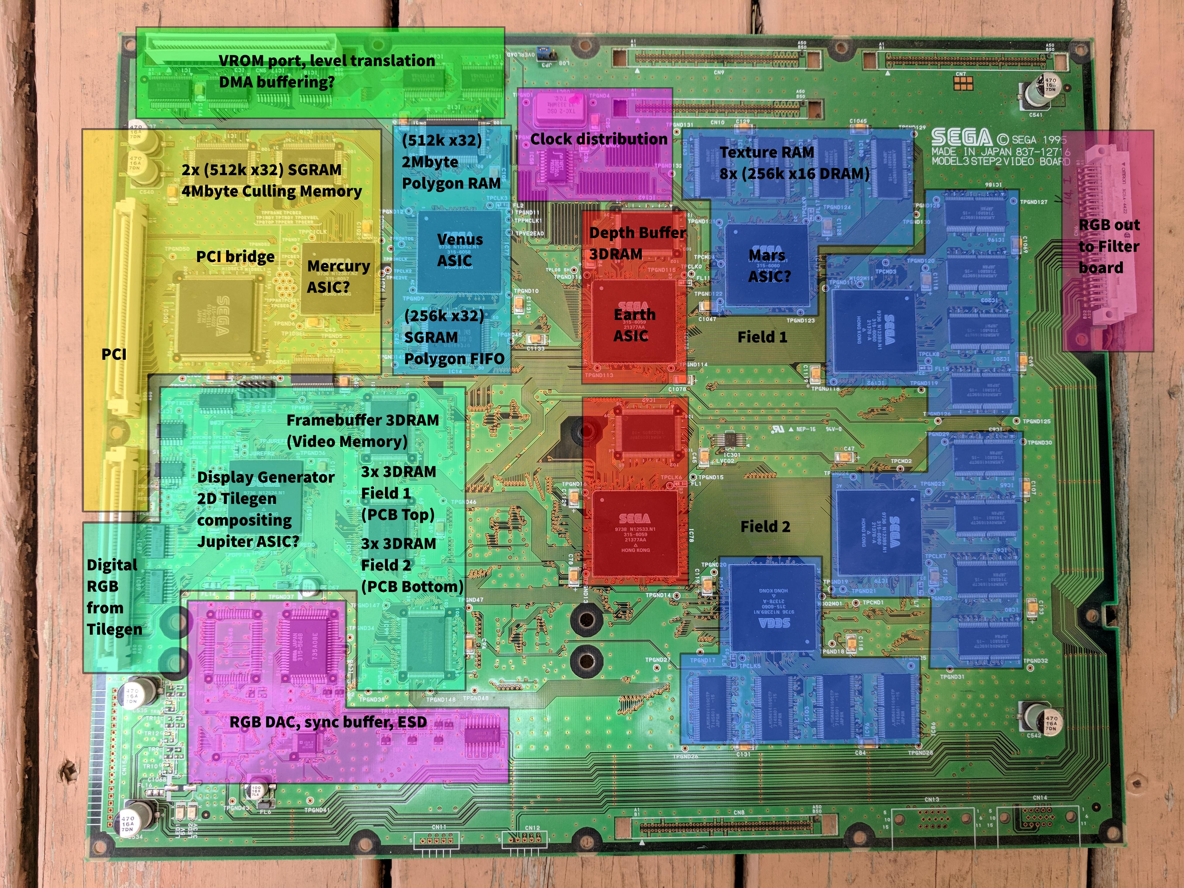
I did look at jtag myself but didn't get especially far with it. Mostly trying to understand what is jtag and how does it work. I did note though that the video board at least has physical jtag pins on it.
You can see here (left hand side between yellow and green section)
https://i.imgur.com/n42LCxO.jpeg
So it would probably be possible to hook something up and get the board to read out some information.
- Ian
- Posts: 2044
- Joined: Tue Feb 23, 2016 9:23 am
Re: How to implement JTAG properly
![]() by model3man » Mon Feb 07, 2022 8:56 pm
by model3man » Mon Feb 07, 2022 8:56 pm
I can get live jtag protocol dumps from my Daytona2 boards.
The file format will be from Saleae Logic, which will be a zipped binary dump of the waveforms.
You can download the software for free and it has JTAG protocol decode so you can step through it yourself. It could be as long as you want - just the bootup, or the first 30 seconds of gameplay, if there is a specific scene change in Daytona2 you want to study jtag writes on.
If there is interest I can do this.
- model3man
- Posts: 24
- Joined: Mon Jul 13, 2020 4:15 am
Re: How to implement JTAG properly
![]() by Bart » Mon Feb 07, 2022 9:41 pm
by Bart » Mon Feb 07, 2022 9:41 pm
model3man wrote:I can get live jtag protocol dumps from my Daytona2 boards.
The file format will be from Saleae Logic, which will be a zipped binary dump of the waveforms.
You can download the software for free and it has JTAG protocol decode so you can step through it yourself. It could be as long as you want - just the bootup, or the first 30 seconds of gameplay, if there is a specific scene change in Daytona2 you want to study jtag writes on.
If there is interest I can do this.
That could be incredibly useful. In particular, I think it would be really interesting to go through diagnostics (VROM test and others) to be able to properly emulate that.
-
Bart - Site Admin
- Posts: 3086
- Joined: Thu Sep 01, 2011 2:13 pm
- Location: Reno, Nevada
Re: How to implement JTAG properly
![]() by model3man » Tue Feb 08, 2022 5:14 pm
by model3man » Tue Feb 08, 2022 5:14 pm
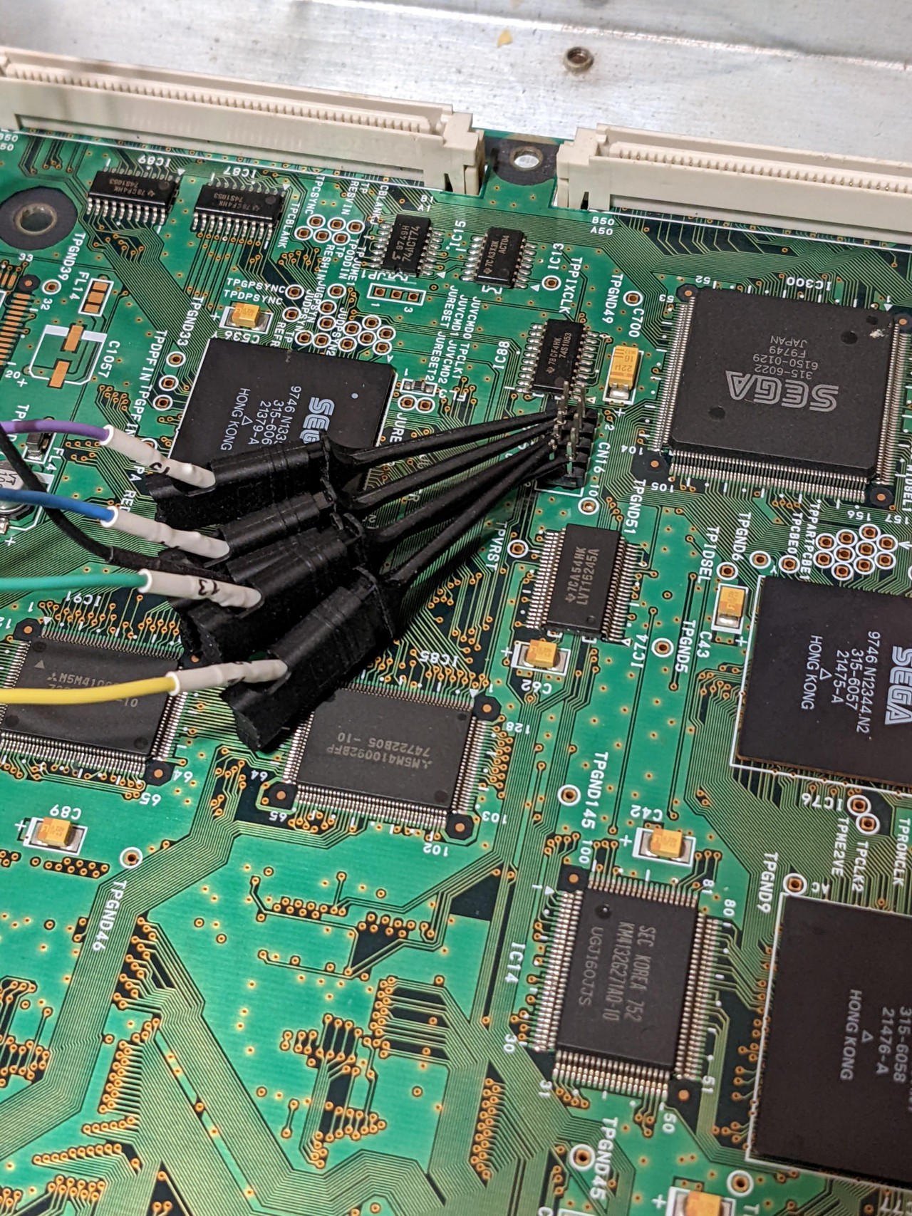
Ok, will do. I've found the PCI connector has the jtag pins and these seem to be wired up, so I'll try those.
I have Sega Rally 2 and Lost World boardsets on the way so i can also get jtag dumps from those also.
I have Sega Rally 2 and Lost World boardsets on the way so i can also get jtag dumps from those also.
- model3man
- Posts: 24
- Joined: Mon Jul 13, 2020 4:15 am
Re: How to implement JTAG properly
![]() by Bart » Wed Feb 09, 2022 12:52 am
by Bart » Wed Feb 09, 2022 12:52 am
model3man wrote:Ok, will do. I've found the PCI connector has the jtag pins and these seem to be wired up, so I'll try those.
I have Sega Rally 2 and Lost World boardsets on the way so i can also get jtag dumps from those also.
That would be an amazing resource. Even if we don't make immediate use of it, it will undoubtedly be looked at at some point.
-
Bart - Site Admin
- Posts: 3086
- Joined: Thu Sep 01, 2011 2:13 pm
- Location: Reno, Nevada
Re: How to implement JTAG properly
![]() by Ian » Fri Feb 11, 2022 2:54 pm
by Ian » Fri Feb 11, 2022 2:54 pm
I've sketched out a rough update for the jtag class ..
It's not complete, also not plugged it into anything yet.
and actual code
JTAG devices linked together almost behave like 1 device it seems. Or the linked devices behave as 1 giant shift register. Anyway this should shift the correct values into the next device.
The output also comes out of the end of the linked list (ie from the last device).
We might need some virtual functions for device specific stuff. But the constructor at least should handle the different width registers.
I suggest we just get the relevant classes to just inherit the functionality, then we can link them together, adding some dummy classes if necessary for ram chips etc.
It's not complete, also not plugged it into anything yet.
- Code: Select all
class JTAG
{
public:
    JTAG(int registerWidth);    // instruction register width
    void Write(bool tck, bool tms, bool tdi, bool trst);
    bool Read();        // return tdo

    void AttachNextDevice(JTAG* next);

private:

    enum class TapState : uint8_t
    {
        TestLogicReset, // 0
        RunTestIdle,    // 1
        SelectDRScan,   // 2
        CaptureDR,      // 3
        ShiftDR,        // 4
        Exit1DR,        // 5
        PauseDR,        // 6
        Exit2DR,        // 7
        UpdateDR,       // 8
        SelectIRScan,   // 9
        CaptureIR,      // 10
        ShiftIR,        // 11
        Exit1IR,        // 12
        PauseIR,        // 13
        Exit2IR,        // 14
        UpdateIR        // 15
    };

    const TapState nextTapState[16][2] =
    {
        // tms = 0      tms = 1
        { TapState::RunTestIdle,  TapState::TestLogicReset }, // 0  Test-Logic/Reset
        { TapState::RunTestIdle,  TapState::SelectDRScan },   // 1  Run-Test/Idle
        { TapState::CaptureDR,    TapState::SelectIRScan },   // 2  Select-DR-Scan
        { TapState::ShiftDR,      TapState::Exit1DR },        // 3  Capture-DR
        { TapState::ShiftDR,      TapState::Exit1DR },        // 4  Shift-DR
        { TapState::PauseDR,      TapState::UpdateDR },       // 5  Exit1-DR
        { TapState::PauseDR,      TapState::Exit2DR },        // 6  Pause-DR
        { TapState::ShiftDR,      TapState::UpdateDR },       // 7  Exit2-DR
        { TapState::RunTestIdle,  TapState::SelectDRScan },   // 8  Update-DR
        { TapState::CaptureIR,    TapState::TestLogicReset }, // 9  Select-IR-Scan
        { TapState::ShiftIR,      TapState::Exit1IR },        // 10 Capture-IR
        { TapState::ShiftIR,      TapState::Exit1IR },        // 11 Shift-IR
        { TapState::PauseIR,      TapState::UpdateIR },       // 12 Exit1-IR
        { TapState::PauseIR,      TapState::Exit2IR },        // 13 Pause-IR
        { TapState::ShiftIR,      TapState::UpdateIR },       // 14 Exit2-IR
        { TapState::RunTestIdle,  TapState::SelectDRScan }    // 15 Update-IR
    };

    void WriteTopBit(uint32_t& reg, bool bit);
    JTAG* GetLastJtag();

    // instruction registers
    uint32_t    m_regInstruction;

    // data registers
    uint32_t    m_regBSR;           // this is the main testing data register. It is used to move data to and from the I / O pins of a device.
    bool        m_regBypass;        // this is a single - bit register that passes information from TDI to TDO. It allows other devices in a circuit to be tested with minimal overhead
    uint32_t    m_regIDCodes;       // this register contains the ID code and revision number for the device.

    // cached states
    bool        m_lastTck;          // last tick value, used to work out rising / falling edge

    // other states
    TapState    m_tapState;
    int         m_regWidth;

    // outputs
    bool        m_tdo;

    JTAG*       m_nextJtag;
};
and actual code
- Code: Select all
JTAG::JTAG(int registerWidth) :
    m_regWidth(registerWidth),
    m_regInstruction(-1),
    m_regBSR(0),
    m_regBypass(false),
    m_regIDCodes(0),
    m_lastTck(false),
    m_tapState(TapState::TestLogicReset),
    m_nextJtag(nullptr),
    m_tdo(false)
{
}

void JTAG::Write(bool tck, bool tms, bool tdi, bool trst)
{
    bool risingEdge = tck && !m_lastTck;
    bool fallingEdge = !tck && m_lastTck;

    m_tdo = tdi;    // assume pass through to start?

    // some logic
    switch (m_tapState)
    {
    case TapState::TestLogicReset:
        m_regInstruction = -1;      // bypass instruction
        break;
    case TapState::RunTestIdle:
        break;
    case TapState::SelectDRScan:
        break;
    case TapState::CaptureDR:
        break;
    case TapState::ShiftDR:
        break;
    case TapState::Exit1DR:
        break;
    case TapState::PauseDR:
        break;
    case TapState::Exit2DR:
        break;
    case TapState::UpdateDR:
        break;
    case TapState::SelectIRScan:
        break;
    case TapState::CaptureIR:
        if (risingEdge) {
            m_regInstruction = (m_regInstruction & -4) | 1;     // 01 loaded into shift register at least significant bits. Should it be msb bits? Spec says bit combination just has to end in 01, ram chips use 1001. This should default to bypass
        }
        break;
    case TapState::ShiftIR:
        if (risingEdge) {
            // get lsb bit
            bool bit = m_regInstruction & 1;
            // shift to the right 1
            m_regInstruction >>= 1;
            // write top bit
            WriteTopBit(m_regInstruction, tdi);
            // update tdi for next jtag chip
            m_tdo = bit;
        }
        break;
    case TapState::Exit1IR:
        break;
    case TapState::PauseIR:
        break;
    case TapState::Exit2IR:
        break;
    case TapState::UpdateIR:
        if (fallingEdge) {
            // current instruction should be updated here
        }
        break;
    }

    m_lastTck = tck;

    if (risingEdge) {
        m_tapState = nextTapState[(int)m_tapState][tms];
    }

    if (m_nextJtag) {
        m_nextJtag->Write(tck, tms, m_tdo, trst);
    }
}

bool JTAG::Read()
{
    // tdo comes from the last chip
    auto last = GetLastJtag();

    return last->m_tdo;
}

void JTAG::AttachNextDevice(JTAG* next)
{
    auto last = GetLastJtag();

    last->m_nextJtag = next;        // add device to the end
}

void JTAG::WriteTopBit(uint32_t& reg, bool bit)
{
    int bitCast = bit;  // otherwise compiler moans
    reg ^= (-bitCast ^ reg) & (1UL << (m_regWidth - 1));
}

JTAG* JTAG::GetLastJtag()
{
    auto last = this;
    while (last->m_nextJtag != nullptr) {
        last = last->m_nextJtag;
    }

    return last;
}
JTAG devices linked together almost behave like 1 device it seems. Or the linked devices behave as 1 giant shift register. Anyway this should shift the correct values into the next device.
The output also comes out of the end of the linked list (ie from the last device).
We might need some virtual functions for device specific stuff. But the constructor at least should handle the different width registers.
I suggest we just get the relevant classes to just inherit the functionality, then we can link them together, adding some dummy classes if necessary for ram chips etc.
- Ian
- Posts: 2044
- Joined: Tue Feb 23, 2016 9:23 am
Re: How to implement JTAG properly
![]() by Bart » Fri Feb 11, 2022 6:00 pm
by Bart » Fri Feb 11, 2022 6:00 pm
Seems sound to me. Another option besides inheritance would be passing in an std::function<> that you want called when an instruction is parsed. Then e.g. Real3D.cpp would implement a JTAG callback, as would the tilegen or whoever else, etc.
-
Bart - Site Admin
- Posts: 3086
- Joined: Thu Sep 01, 2011 2:13 pm
- Location: Reno, Nevada
Re: How to implement JTAG properly
![]() by model3man » Sat Feb 12, 2022 8:04 pm
by model3man » Sat Feb 12, 2022 8:04 pm
Ok, I've got some logs with Daytona2 Power Edition.
JTCK clock rate is 1mhz.
https://ufile.io/seuha9b0
You need saleae logic to view the files. I don't know if the protocol analyzer settings are completely correct, but the pin assignments should be.
Tests are:
1. Booting the board, and letting the game start and intro run.
IMPORTANT: Data lines which are normally high take a while to go high. DO NOT interpret this as JTAG traffic, since it is not.
Simply ignore all the noise as the lines go to their high state.
I let the attract mode run for 60sec but no further JTAG activity happened.
2. Service menu - RAM TESTS
All the ram tests on the board passed. When it tests, there is loads of JTAG traffic as it tests first video RAM, and then ROMs.
3. Service menu - BOUNDARY SCAN TEST
Whatever tests are done on jtag, it does here, and the board is happy with 0 errors.
Here is the boot screen of this board:
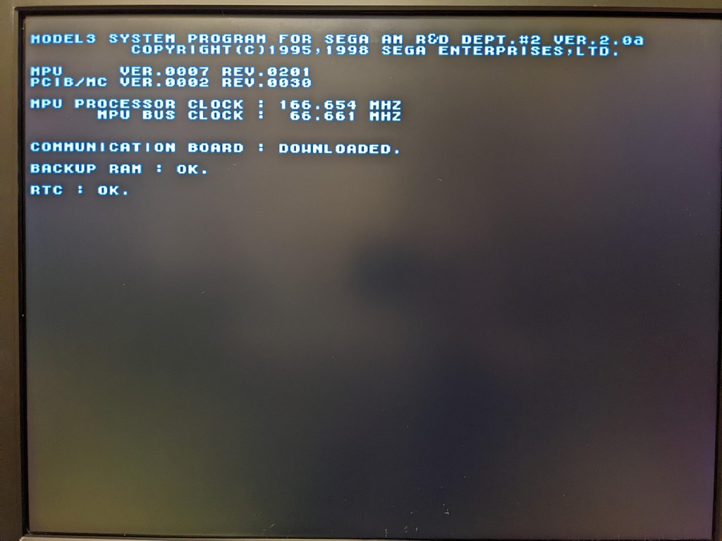
Note that on a cold boot, this screen may not be visible as it may depend on some prior jtag state. Or maybe it's just my upscaler taking a split second to miss it.
JTCK clock rate is 1mhz.
https://ufile.io/seuha9b0
You need saleae logic to view the files. I don't know if the protocol analyzer settings are completely correct, but the pin assignments should be.
Tests are:
1. Booting the board, and letting the game start and intro run.
IMPORTANT: Data lines which are normally high take a while to go high. DO NOT interpret this as JTAG traffic, since it is not.
Simply ignore all the noise as the lines go to their high state.
I let the attract mode run for 60sec but no further JTAG activity happened.
2. Service menu - RAM TESTS
All the ram tests on the board passed. When it tests, there is loads of JTAG traffic as it tests first video RAM, and then ROMs.
3. Service menu - BOUNDARY SCAN TEST
Whatever tests are done on jtag, it does here, and the board is happy with 0 errors.
Here is the boot screen of this board:
Note that on a cold boot, this screen may not be visible as it may depend on some prior jtag state. Or maybe it's just my upscaler taking a split second to miss it.
- model3man
- Posts: 24
- Joined: Mon Jul 13, 2020 4:15 am
12 posts
• Page 1 of 2 • 1, 2
Who is online
Users browsing this forum: No registered users and 1 guest