There are 3 frame buffers. 1 opaque and 2 for the transparent layers. Each depth tests separately.
So..
496×384 × 4 bytes per pixel is 671k
And also a depth buffer. Depth buffer is 24 bits probably with packed stencil too.
So
496×384 × 4 bytes per pixel so 671k
(671 ×2) × 3 frame buffers is 4.5meg of ram. That's not even counting memory memory for page flipping. Potentially would need another 1.5meg for a final two buffers for composition.
I mean it's possible the architecture doesn't work like this at all. But the result is perfect for every game. Seems an overly expensive solution.
Model3 annotated board photos
Forum rules
Keep it classy!
Keep it classy!
- No ROM requests or links.
- Do not ask to be a play tester.
- Do not ask about release dates.
- No drama!
36 posts
• Page 2 of 4 • 1, 2, 3, 4
Re: Model3 annotated board photos
![]() by Ian » Wed Jul 29, 2020 12:45 am
by Ian » Wed Jul 29, 2020 12:45 am
- Ian
- Posts: 2044
- Joined: Tue Feb 23, 2016 9:23 am
Re: Model3 annotated board photos
![]() by Hydreigon233 » Fri Jul 31, 2020 9:05 am
by Hydreigon233 » Fri Jul 31, 2020 9:05 am
Lost World Jurassic Park can use the Sega custom 315-5649 I/O Controller's RS-422 bus to communicate with with the older optical gun I/O board used in Virtua Cop 2 and House of the Dead 1. On startup, there would be an additional message saying "Download Complete" if the older gun I/O board is connected to the Model 3's RS-422 bus. The calibration screen is also different too with a blue screen. No download message appears if a gun sense board is plugged in. I'm certain Sega Bass Fishing Deluxe cabs also use the RS-422 bus to communicate with its KL5C80A16 based I/O board for its more detailed fishing controls.model3man wrote:Bart wrote:I'm curious about the Lost World guns. There are apparently two variants, neither of which I've seen the boards for. One variant apparently uses analog guns but one variant uses some sort of a serial interface. How are these connected to the Model 3 board? If it's a bidirectional interface, that would solve our problems. If it turns out that some Model 3 boards actually use an RS232 interface for light guns or other controls, that would be a big deal. I can easily code up a ROM that accepts arbitrary data from a PC, allowing us to quickly test anything we want.
http://solid-orange.com/1611
The lightguns appear to just output analog 0-5v for the X/Y axes with a digital signal for "Gun pointed at screen or not". Some later versions for other platforms seem to only output serial.
-

Hydreigon233 - Posts: 22
- Joined: Mon Aug 14, 2017 7:13 pm
Re: Model3 annotated board photos
![]() by model3man » Sun Aug 02, 2020 2:18 am
by model3man » Sun Aug 02, 2020 2:18 am
That's interesting. I completely forgot about that. The RS-422 bus is also (I think) used for MIDI commands to the DSB board, though in that case it is unidirectional only.
So studying Lost World's code should reveal how the tx/rx registers are configured. A RS422 to RS232 converter box is about $30 and you could wire it in. Bart might be onto something.
So studying Lost World's code should reveal how the tx/rx registers are configured. A RS422 to RS232 converter box is about $30 and you could wire it in. Bart might be onto something.
- model3man
- Posts: 24
- Joined: Mon Jul 13, 2020 4:15 am
Re: Model3 annotated board photos
![]() by icuk7 » Sun Aug 02, 2020 2:53 pm
by icuk7 » Sun Aug 02, 2020 2:53 pm
Awesome work!
I have some faulty boards, some severe and some very slight. Is it possible to recreate in Supermodel the effects of faulty ram chips or faulty custom processors?
This would be extremely useful for faultfinding real hardware where the different games service menu tests fail.
Would desoldering everything off a board be useful for chip ID?
I may have a CPU + Videoboard in storage that's beyond repair I could sacrifice for info.
Thanks.
- icuk7
- Posts: 24
- Joined: Sun Mar 13, 2016 8:59 am
Re: Model3 annotated board photos
![]() by Bart » Sun Aug 02, 2020 11:42 pm
by Bart » Sun Aug 02, 2020 11:42 pm
model3man wrote:That's interesting. I completely forgot about that. The RS-422 bus is also (I think) used for MIDI commands to the DSB board, though in that case it is unidirectional only.
So studying Lost World's code should reveal how the tx/rx registers are configured. A RS422 to RS232 converter box is about $30 and you could wire it in. Bart might be onto something.
I only have VF3's I/O panel and I don't recall this connector being exposed there. Are there photos of the Lost World I/O panel or wherever the connector is located? There is indeed a space for such a connector on the main board but I wonder if it is already being exposed on the I/O panel...
We know enough to simulate reading the guns in the emulator. I don't think a standard UART is used, unfortunately. So it would still take some work to figure out how to talk through the port but it's definitely an interesting idea. Maybe P1_P2.bin from the Pro-1000 uses it? Although I would suppose it talks over SCSI.
-

Bart - Site Admin
- Posts: 3086
- Joined: Thu Sep 01, 2011 2:13 pm
- Location: Reno, Nevada
Re: Model3 annotated board photos
![]() by Bart » Sun Aug 02, 2020 11:46 pm
by Bart » Sun Aug 02, 2020 11:46 pm
icuk7 wrote:Awesome work!
I have some faulty boards, some severe and some very slight. Is it possible to recreate in Supermodel the effects of faulty ram chips or faulty custom processors?
This would be extremely useful for faultfinding real hardware where the different games service menu tests fail.
Hmm... not really. Certainly not electrical faults, which might have very peculiar behavior. You would have to have a lot of information on the kind of fault you are modeling. For example, faulty RAM chips... you would have to corrupt the same addresses in the same way. And we don't really do a chip-level emulation but rather a "system-level" emulation that attempts to produce the same outputs as the chips but the process by which we get there is not at all similar to what the hardware is likely doing.
Would desoldering everything off a board be useful for chip ID?
I may have a CPU + Videoboard in storage that's beyond repair I could sacrifice for info.
Thanks.
I don't think so but I do appreciate the offer. The boards might come in handy for something so I wouldn't toss them just yet, though
-
Bart - Site Admin
- Posts: 3086
- Joined: Thu Sep 01, 2011 2:13 pm
- Location: Reno, Nevada
Re: Model3 annotated board photos
![]() by model3man » Mon Aug 03, 2020 2:40 am
by model3man » Mon Aug 03, 2020 2:40 am
Virtua Fighter 3 has many of connectors unsoldered, but you can just add them.
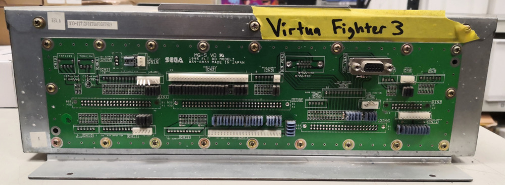
The RS422 port is the very bottom left. The part that is missing can be soldered in, but then you have to also buy its mating connector and crimp your own harness.
https://www.digikey.com/product-detail/ ... ND/1885773
However, the MIDI port is actually at the top right! It is also differential, probalby also RS422. Both channels probable live in the same I/O chip, but I'm making assumptions.
So I would just solder wires to it anyway, since you will need them for the RS422 converter box. MIDI is uart-based so if you pick a game with DSB you will at least get TX UART figured out I think.
315-5649 code from MAME:
https://github.com/mamedev/mame/blob/ma ... 5_5649.cpp
There are mentions of it being 8251-compatible register wise
- model3man
- Posts: 24
- Joined: Mon Jul 13, 2020 4:15 am
Re: Model3 annotated board photos
![]() by Bart » Mon Aug 03, 2020 10:28 am
by Bart » Mon Aug 03, 2020 10:28 am
315-5649 drives the DSB board interface? I emulated it as a simple FIFO but I should go check and see if there are any registers nearby that are set up by the system and behave like the 8251. Argh... I need to find time  This all sounds like a potentially very promising approach.
-
Bart - Site Admin
- Posts: 3086
- Joined: Thu Sep 01, 2011 2:13 pm
- Location: Reno, Nevada
Re: Model3 annotated board photos
![]() by icuk7 » Tue Aug 04, 2020 2:59 pm
by icuk7 » Tue Aug 04, 2020 2:59 pm
Ah, OK, thanks for the clarification Bart. 
I have a faulty Videoboard with a texture issue and was hoping to narrow down if it was a specific Ram chip.
Is this picture any help?
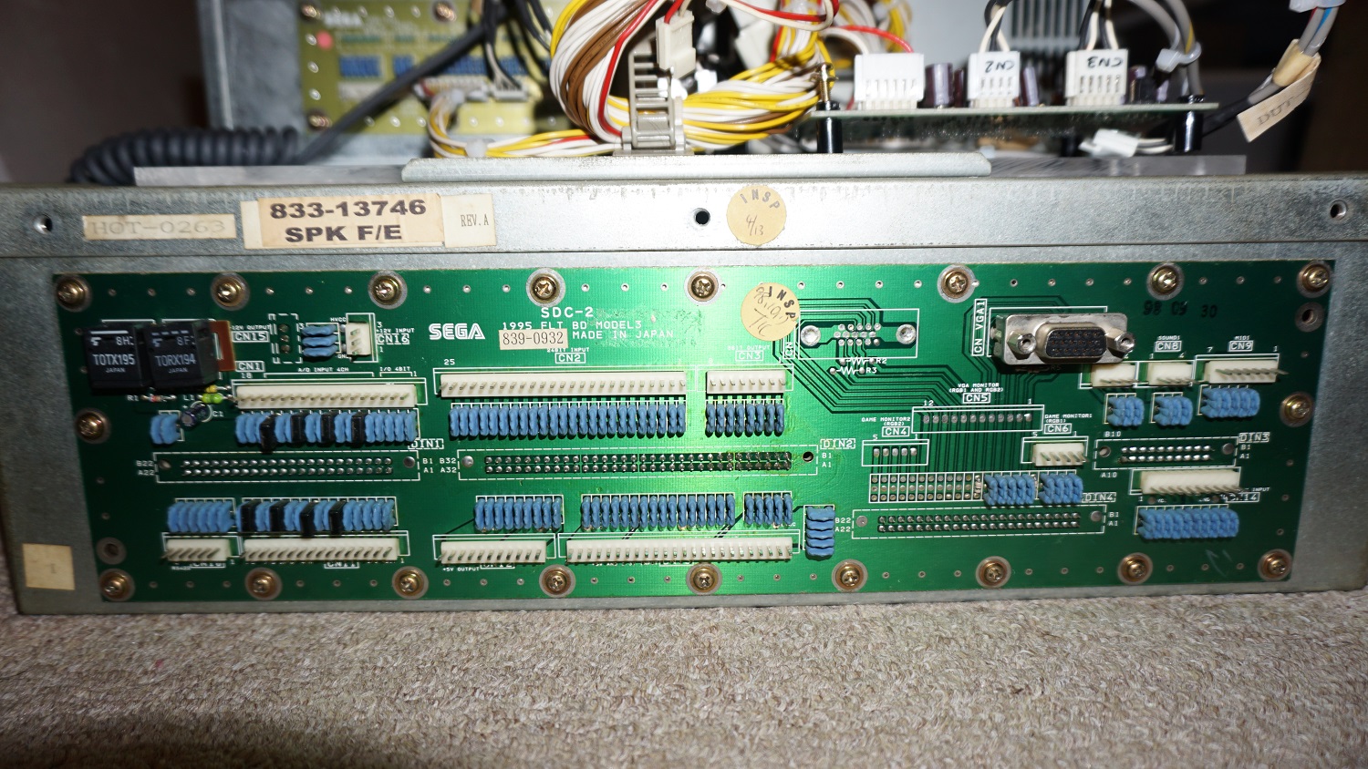
On Daytona 2, SpikeOut and Sega Rally 2 the DSB2 is connected to CN9, top right.
I have a faulty Videoboard with a texture issue and was hoping to narrow down if it was a specific Ram chip.
Is this picture any help?
On Daytona 2, SpikeOut and Sega Rally 2 the DSB2 is connected to CN9, top right.
- icuk7
- Posts: 24
- Joined: Sun Mar 13, 2016 8:59 am
Re: Model3 annotated board photos
![]() by Bart » Tue Aug 04, 2020 7:33 pm
by Bart » Tue Aug 04, 2020 7:33 pm
Thanks! This looks exactly like the board I have. I think it's definitely worth looking into how the MIDI port might be configured in software. I need to look more closely at whether the MIDI port looks like an Intel 8251... I really should get a logic analyzer to see if I can intercept commands.
-
Bart - Site Admin
- Posts: 3086
- Joined: Thu Sep 01, 2011 2:13 pm
- Location: Reno, Nevada
36 posts
• Page 2 of 4 • 1, 2, 3, 4
Who is online
Users browsing this forum: No registered users and 0 guests