Layered transparency
Forum rules
Keep it classy!
Keep it classy!
- No ROM requests or links.
- Do not ask to be a play tester.
- Do not ask about release dates.
- No drama!
43 posts
• Page 4 of 5 • 1, 2, 3, 4, 5
Re: Layered transparency
![]() by Ian » Sun Apr 23, 2017 9:20 am
by Ian » Sun Apr 23, 2017 9:20 am
One thing I haven't checked is.. We are skipping I think the sibling pointers, if the node has a colour table attached. Those pointers look valid. Wonder what they are pointing too. The original code also had this check, I think it stopped circular references or some other bug.
- Ian
- Posts: 2044
- Joined: Tue Feb 23, 2016 9:23 am
Re: Layered transparency
![]() by Ian » Mon Apr 24, 2017 4:27 pm
by Ian » Mon Apr 24, 2017 4:27 pm
Well I had a bit more time for the ocean hunter issue .. I basically figured it out.
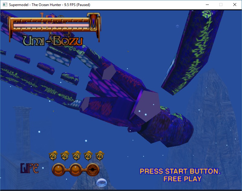
This model should be 100% transparent
Removed poly transparency so you can see the full model (also textures)
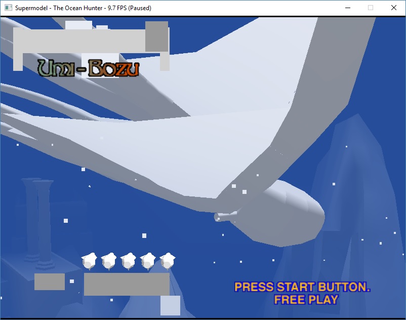
I marked the polygons with lodTablePointer > 0. Never seen this used anywhere else, it's always zero which is the first entry in the blend table. Ie default values

The polys which should be transparent perfectly match the polys using the blend table values.
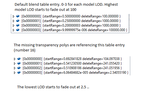
This is what the blend table entries look like
This model should be 100% transparent
Removed poly transparency so you can see the full model (also textures)
I marked the polygons with lodTablePointer > 0. Never seen this used anywhere else, it's always zero which is the first entry in the blend table. Ie default values
The polys which should be transparent perfectly match the polys using the blend table values.
This is what the blend table entries look like
- Ian
- Posts: 2044
- Joined: Tue Feb 23, 2016 9:23 am
Re: Layered transparency
![]() by Ian » Tue Apr 25, 2017 1:45 pm
by Ian » Tue Apr 25, 2017 1:45 pm
reading the docs for node blending
So it's just a simple distance compare against the eye point or 0,0,0
LOD blending is also used to smoothly eliminate graphic objects that are too small to provide any meaningful contribution to the scene being rendered. This is done by using translucency to fade the object out of the rendered scene as a function of distance from the eyepoint, and then completely discarding the object from the display list at run-time.
So it's just a simple distance compare against the eye point or 0,0,0
- Ian
- Posts: 2044
- Joined: Tue Feb 23, 2016 9:23 am
Re: Layered transparency
![]() by MakutaMaster962 » Tue Apr 25, 2017 2:28 pm
by MakutaMaster962 » Tue Apr 25, 2017 2:28 pm
Excellent work in finding out what the problem was with Umi-Bozu.  Now, I know you've got other things besides this particular issue to focus on, but how soon can I expect a fix for this issue? Sorry if I sound too demanding.
- MakutaMaster962
- Posts: 20
- Joined: Wed Mar 08, 2017 7:50 am
Re: Layered transparency
![]() by Ian » Tue Apr 25, 2017 3:05 pm
by Ian » Tue Apr 25, 2017 3:05 pm
It will be done if i can figure out the missing details
- Ian
- Posts: 2044
- Joined: Tue Feb 23, 2016 9:23 am
Re: Layered transparency
![]() by Bart » Tue Apr 25, 2017 6:45 pm
by Bart » Tue Apr 25, 2017 6:45 pm
Awesome work, Ian! The blend table values you list are a bit confusing. I'm assuming the game is explicitly using the lowest LOD for this feature and "abusing" the mechanism in general. To be used for smooth LOD I would assume that each delete range would be equal or near to the next level's start range but that's clearly not happening here.
In the default table, the end ranges make sense -- they increase monotonically -- but the start ranges decrease. Presumably they are not encoded as simple distances but a multiplier of the end range or something? The numbers still don't quite work out though.
In the default table, the end ranges make sense -- they increase monotonically -- but the start ranges decrease. Presumably they are not encoded as simple distances but a multiplier of the end range or something? The numbers still don't quite work out though.
-

Bart - Site Admin
- Posts: 3086
- Joined: Thu Sep 01, 2011 2:13 pm
- Location: Reno, Nevada
Re: Layered transparency
![]() by Ian » Wed Apr 26, 2017 2:34 am
by Ian » Wed Apr 26, 2017 2:34 am
Yeah it does look to me they are abusing the LOD feature to do blending. But you are right, the values don't make 100% sense.
In the SDK values are specified as subtended angles, or distances
Distances are written like this ..
In short it looks like
start_value = 1/delete_range
delete_value = 1 / (1/start_range - 1/delete_range)
The method that sends subtended angles look nearly identical, but with angles instead.
I don't see any code or methods to switch between using the values as angles, or using them as ranges. And the ranges produced by that method don't really make sense.
One thing I did note though from the raw data is the max distance ..
Culling nodes seem to have a distance capped at 100,000
The SDK has code that looks like this
Although the node distances can actually end up larger, if the model matrix has a scaling value
In the SDK values are specified as subtended angles, or distances
Distances are written like this ..
- Code: Select all
signed int __thiscall PRO_LOD_Table::SetRangeBlendParameters(int this, int feature_type, int lod_number, float start_range, float delete_range)
{
  int v5; // edx@1
  signed int result; // eax@2
  float swap; // ST08_4@4
  double v8; // st7@9
  int v9; // edx@12
  double v10; // st7@12
  int v11; // edx@15
  long double v12; // st7@15
  double v13; // st7@17
  float v14; // [sp+8h] [bp-4h]@15

  v5 = feature_type;
  if ( *(_DWORD *)(this + 112) > feature_type )
  {
    // sanity check paramaters
    if ( delete_range < (double)start_range )
    {
      swap = start_range;
      start_range = delete_range;
      delete_range = swap;
    }

    // checking for valid floats?
    if ( !(LODWORD(start_range) & 0x7FFFFFFF) )
      start_range = 0.0000001;
    if ( !(LODWORD(delete_range) & 0x7FFFFFFF) )
      delete_range = 0.0000001;

    v8 = delete_range;
    v8 = 1.0 / v8;
    v9 = 8 * (lod_number + 4 * v5);                  // calculate array address to write to
    *(float *)(*(_DWORD *)(this + 28) + v9) = v8;    // write start range here, although seems to be 1/delete_range ?

    v10 = start_range;
    v10 = 1.0 / v10;
    v11 = *(_DWORD *)(this + 28) + v9;
    v12 = v10 - *(float *)v11;                       // (1/start_range) - (1/delete_range)
    v14 = v12;
    if ( fabs(v12) < 0.0000001 )
      v14 = 0.0000001;
    v13 = v14;
    v13 = 1.0 / v13;                                 // (1 / v12)
    *(float *)(v11 + 4) = v13;                       // write result
    PRO_Culling_Data_Block::NotifyUpdate((PRO_Culling_Data_Block *)this);
    result = 1;
  }
  else
  {
    result = 2;
  }
  return result;
}
In short it looks like
start_value = 1/delete_range
delete_value = 1 / (1/start_range - 1/delete_range)
The method that sends subtended angles look nearly identical, but with angles instead.
I don't see any code or methods to switch between using the values as angles, or using them as ranges. And the ranges produced by that method don't really make sense.
One thing I did note though from the raw data is the max distance ..
Culling nodes seem to have a distance capped at 100,000
The SDK has code that looks like this
- Code: Select all
              if ( PRO_Polygon::GetMaxBoundingBoxDimension((PRO_Polygon *)v7) > 100000.0 )
                PRO_Culling_Node::fracturePolygon(v42, (struct PRO_Polygon *)v7, v41, *((_DWORD *)v41 + 1) - 1);
Although the node distances can actually end up larger, if the model matrix has a scaling value
- Ian
- Posts: 2044
- Joined: Tue Feb 23, 2016 9:23 am
Re: Layered transparency
![]() by HarryTuttle » Wed Apr 26, 2017 11:56 am
by HarryTuttle » Wed Apr 26, 2017 11:56 am
Excellent work Ian!
That could also fix the ambulance trails scene in ECA, and the distant details of the Death Star trench run in SWT.
That could also fix the ambulance trails scene in ECA, and the distant details of the Death Star trench run in SWT.
-

HarryTuttle - Posts: 646
- Joined: Thu Mar 09, 2017 8:57 am
Re: Layered transparency
![]() by Ian » Wed May 10, 2017 2:55 am
by Ian » Wed May 10, 2017 2:55 am
I had a debug of the shadows in virtua fighter 3, since it's a step 1 game, and there is no extra information in the culling nodes which cuts down some possibilities about what the h/w could be doing.
I had to hack Nik's program to override the clear colour.. because the background colour is black, and it makes the shadows invisible. Anway, overriding the clear colour we can now see the shadow polys
Here's a few shadow polys, you can see 1 pixel of z fighting in the image if you look close enough.
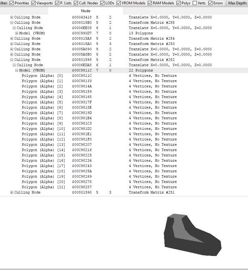
Anyway, this is what the models look like without the model matrix
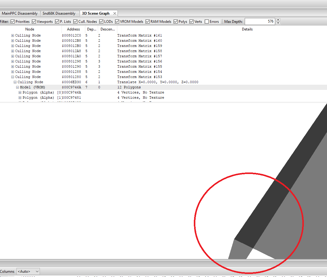
The models are actually 3 dimensional, and are not flat at all. They are using a special matrix to flatten the model in the Y direction making the models completely planar.
My best guess without doing more debugging is, the hardware is detecting this special matrix which flattens the models and turns on stenciling for them, as there is nothing else in the nodes, or the polygons themselves which would indicate they need to be stenciled. This flatten matrix would always result in co-planar polys, which would lead to Z fighting if they overlap.
I had to hack Nik's program to override the clear colour.. because the background colour is black, and it makes the shadows invisible. Anway, overriding the clear colour we can now see the shadow polys
Here's a few shadow polys, you can see 1 pixel of z fighting in the image if you look close enough.
Anyway, this is what the models look like without the model matrix
The models are actually 3 dimensional, and are not flat at all. They are using a special matrix to flatten the model in the Y direction making the models completely planar.
My best guess without doing more debugging is, the hardware is detecting this special matrix which flattens the models and turns on stenciling for them, as there is nothing else in the nodes, or the polygons themselves which would indicate they need to be stenciled. This flatten matrix would always result in co-planar polys, which would lead to Z fighting if they overlap.
- Ian
- Posts: 2044
- Joined: Tue Feb 23, 2016 9:23 am
43 posts
• Page 4 of 5 • 1, 2, 3, 4, 5
Who is online
Users browsing this forum: No registered users and 1 guest